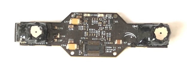
Centeye’s integrated sensors are complete vision modules with one or more vision chips, matching optics, and a processor. The processor is programmed with firmware to operate and acquire visual information from the vision chips, perform any image processing and/or perception algorithms, and package the sensor output into a form usable by a host (such as an autopilot). These are tightly integrated devices optimized for performance and small size. Below is summary information on two recent generations of integrated sensors.
High Dynamic Range Sensor (2019)
New Centeye multi-mode high dynamic range sensor
Developed for miniature / nano drone applications and robotics. All specifications are exemplary and approximate. Actual values may vary.
- Mass: 2.7 grams
- Size: 51 mm by 15 mm
- Power source: 3.6 V to 5.5 V
- Power
draw at 5 V
- 95 mA in default mode
- 125 mA with proximity sensing enabled
- 165 mA with full infrared illumination
- Physical Interface: 20-pin Hirose® DF30 connector and 6-pin JST® XSR connector
- Data Interface: High-speed serial (UART) up to 5 Mbps
- Imaging: RockCreek low light vision chip
- Field of view: 90º (across) with current firmware, up to 140º to 150º possible. Other lens configurations are in development.
- Infrared illumination: 850 nm wavelength, up to 5 m range in pure darkness depending on albedo
- Adaption from bright to dark environments and vice versa: Near instantaneous
- Measurements:
20 to 24 measurement windows over a 70º x 90º field of view each providing
- X and Y accumulated optical flows using a keyframe method (to reduce random walk from noise)
- Stereo distance, practical range about 30cm to 250cm using current lens configuration.
- Stereo distance confidence flags
- Proximity sensing using pulsed light (when enabled)
Intended applications
- Low-mass vision for miniature / nano drones
- Forward depth map to facilitate maneuvering around obstacles
- Used as an array for omnidirectional sensing to support stabilization, omnidirectional obstacle avoidance, and visual odometry using integrated scaled optical flow
Sample Measurement Set #1: Response with Sun in image
This example highlights the ability of the sensor to operate over a large dynamic range. Note that the presence of the Sun in the sensor’s field of view does not wash out the image and prevent detection of nearby obstacles.
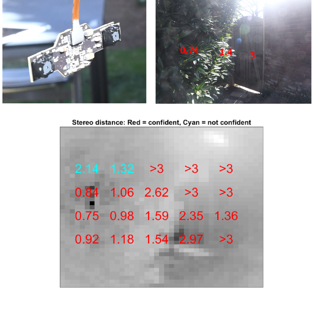
Top Left: Picture of sensor in the Sun
Top Right: Photograph of environment taken from the sensor’s position (using a digital camera). The camera’s field of view is slightly smaller than that of the sensor. Red numbers show actual distances measured with a laser rangefinder.
Bottom: View seen by sensor, showing compressed intensity pixels and 20 distance measurements. Red numbers were “confident” and passed all confidence tests. Cyan numbers failed one or more confidence tests but were often still accurate. Ranges beyond 3 meters were limited.
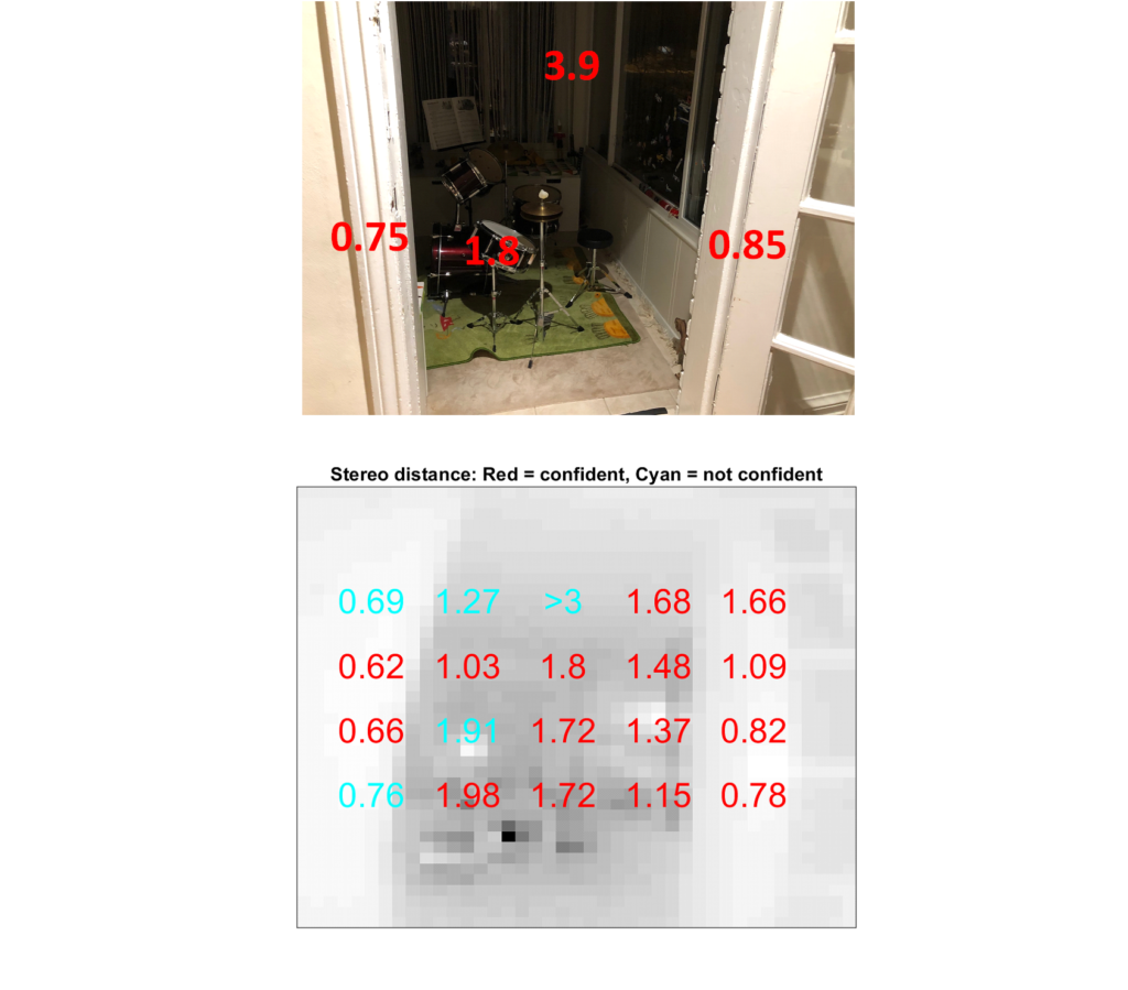
Sample Measurement Set #2: Doorway from bright side
This example shows the sensor viewing a dark interior from an external position with a higher ambient illumination. This example shows what the sensor might see if mounted on a drone directed to fly through a doorway. Note the stereo distance measurements detected safe directions of travel.
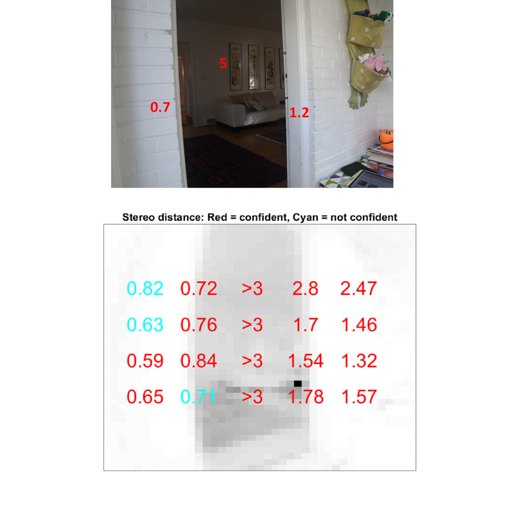
Top: Photograph of environment taken from the sensor’s position (using a digital camera). Red numbers show actual distances measured with a laser rangefinder.
Bottom: View seen by sensor, showing compressed intensity pixels and 20 distance measurements. Red numbers were “confident” and passed all confidence tests. Cyan numbers failed one or more confidence tests but were often still accurate. Ranges beyond 3 meters were limited.
Sample Measurement Set #3: Bush at night
These measurements show a bush illuminated at 1.5 meters and 2.5 meters distance (measured from the sensor to the closest branch), with illumination provided by the IR LEDs. The measured distances were slightly larger in this example due to the varying depth of the bush leaves.
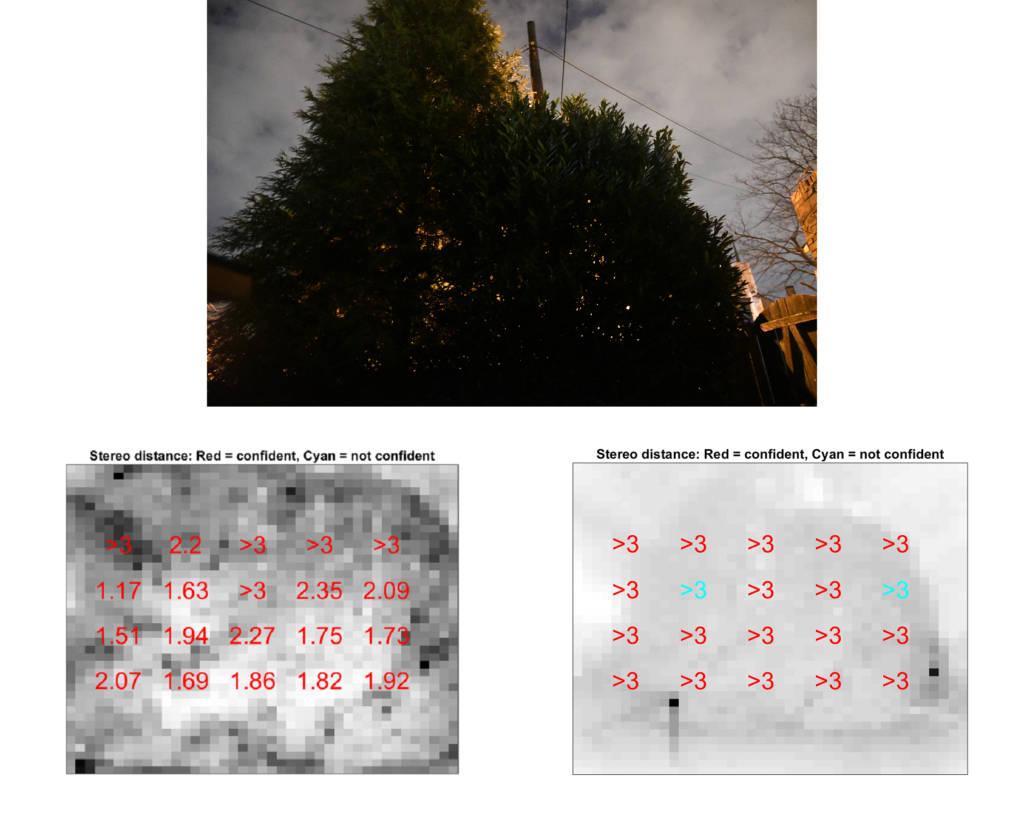
Top: Image of bush taken at 5m with a digital camera (F/3.5, ISO 16000, 1/6 sec exposure, f=16mm).
Middle: View from sensor at 1.5 m, showing compressed intensity pixels and 20 distance measurements. Red numbers were “confident” and passed all confidence tests. All measurements in this example passed all confidence tests due to the high contrast of the stimulus. Ranges beyond 3 m were limited.
Bottom: View seen by sensor at 2.5 m, showing compressed intensity pixels and 20 distance measurements. All measured distances were beyond 3 m and thus clipped. Cyan numbers failed one or more confidence tests but were still accurate.
Sample Measurement Set #4: Doorway from interior at night
This is the same doorway as above but viewed from the other side and at night. Note that the indoor lights were turned off before acquiring sensor measurements.
Top: Photograph of environment taken from the sensor’s position (using digital camera) with indoor lights turned on. Indoor lights were turned off before sensor measurements were acquired. Red numbers show actual distances (ground truth) measured with a laser rangefinder.
Bottom: View from sensor, with indoor lights turned off and illumination provided by IR LEDs, showing compressed intensity pixels and 20 distance measurements. Red numbers were “confident” and passed all confidence tests. Cyan numbers failed one or more confidence tests but were often still accurate. Ranges beyond 3 meters were limited. Measurement windows that contain multiple depths generally produce a distance measurement that is approximately an average of all depths, for example the second column of measurements from the right.
Centeye Multi-Mode Stereo Sensor (2016)
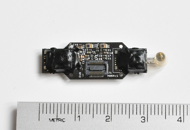
This is the sensor we are using for our work starting in 2016.
- 2 x Centeye RockCreek™ vision chips, with two-mode pixels and analog contrast enhancement/edge detection circuitry
- Custom wide field of view (up to 150°) optics
- Optical flow
- Stereo vision
- Laser ranging
- LED illumination
- Mass: 1.0 grams
- Power: As little as 60 mA @ 4V
- Neural network-based attention modulation
Acknowledgement of Support
“This research was developed in part with funding from the Defense Advanced Research Projects Agency (DARPA) under contract D15PC00165. The views, opinions, and/or findings expressed are those of the author and should not be interpreted as representing the official views or policies of the Department of Defense or the U.S. Government.”
Distribution Statement “A” (Approved for Public Release, Distribution Unlimited)